| The home of the VMCC AJS OHC Register |
|---|
| Home | History | Sales | Wants | Newsletter | Gatherings | Photos | Links |
|---|
| Repairs | Engine | Gearbox | Clutch | Wheels and Frame |
|---|
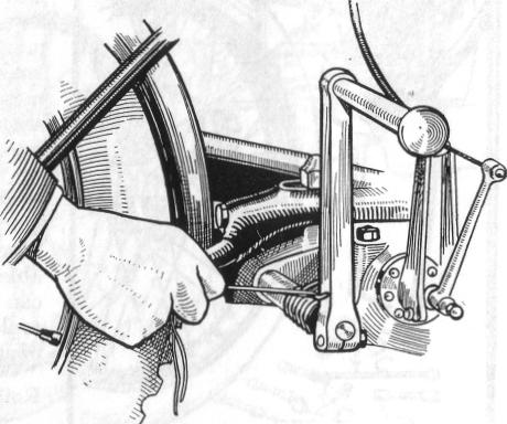
The clutches fitted to A.J.S. gearboxes are either single-plate in the case of the 2.48 and 3.49 h.p., and multi-plate on 4.98 h.p. and twin-cylinder machines (Fig. 16), and in all cases cork insets are used to transmit the drive. The only parts of the clutch likely to show signs of wear are the teeth of the sprocket, the key in the sliding plate on the end of the mainshaft against which operates the long push rod, the lugs on the corked plate and the slots in the sprocket by means of which the corked plate is driven (these last two items only concern multi-plate clutches) and the cork insets themselves.
If the necessary facilities are available for doing this job , the following particulars will be useful. Good quality, closed grained corks should be used and the size must enable them to be pressed in tight, leaving tnot less that a qurater of an inch standing out either side.
Before the corks are pressed into the plate or sprocket, as the case may be, the sides of the corks should be lightly smeared with fish glue or a similar preparation, to enable them to be firmly held in position and placed somewhere warm to dry.
The corks should be machined to the correct length by a V-shaped tool, the corks running at fairly high speed. They should be faced down in all cases, whether fitted to sprocket or plate, until they protrude an eighth of an inch either side.
Under no circumstances should oil be put on the corks: they must run dry.
On multi-plate clutches care should be taken to see when assembling that the corked plate has sufficient lateral movement to be just free between the plates on either side as otherwise clutch drag , causing difficulty in changing gear, may be experienced.
On the 4.98 h.p. and twin-cylinder machines from 1926 provision was made for regulating the lateral movement of this plate. It will be found on the clutch plate fixed to the mainshaft next to the gearbox on some models or the sliding plate on the end of the mainshaft on others that there are four pegs. There will also be seen four adjusting pins, which are secured by a locking device consisting of four short lengths of spring wire which fit in the slots in the heads of the pins.
When the corked plate with the two lugs already referred to has too much lateral movement, this can be adjusted by raising the spring wires out of their slots and screwing the pins up equally until the corked plate is just free.
On clutches where there is no provision for adjusting, the lateral movement should be taken up by recorking the plate.
On all A.J.S. gearboxes u p t o 1929 the footstarter mechanism was fitted on the outside of the gearbox, and with these machines the follow-ing tips may be useful in replacing the foot-starter crank return springs.
On these gearboxes, where one end of the spring is attached to the foot-starter quadrant, proceed as follows (see also Figs. 17 and 17A)
2. Sliding plate (note key in centre which passes through main gearbox shaft).
:3. Fixed plate, with. adjusting pins and locking device.
4. Plate fitted with cork inserts (driven by No. 1).
5. Dished plate (driven by No. 3).
6. Ball bearing on which No. 1 revolves, when clutch is disengaged.
7. Clutch-spring adjusting nut.
8. Clutch spring
After fastening the spring on the outside of the quadrant-shaft bracket, and inserting the quadrant shaft in its bearing, hook the free end of the spring over the top spoke of the quadrant, turn the latter a complete revolution to the right, and now push the quadrant into position, so that the stop on the former engages with that on the chain stay of the frame, at the same time pressing with both thumbs on the outer coils of the spring, down and over the kick-starter shaft bearing.
On 1928 and 1929 2.48 h.p. machines one end of the return spring was hooked round the foot-starter crank, and although not difficult perhaps to fit or remove, the most simple and quickest way is to fasten a stout piece of string on to the hooked end of the spring, and pull the latter inwards and backwards until the hook is released. Fitting the spring is carried out in the same way.
This method will avoid damage to the crank and spring and possibly the hands, if prised off with a screwdriver or similar tool.
On some gearboxes the end of the foot-starter shaft is splined or serrated, and in this case the crank was not definitely positioned. When refitting, the normal position of the crank should be just over the vertical, that is, inclined slightly towards the rear of the machine.
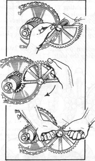
Then turn quadrant a complete revolution in direction of arrow, as seen in the second picture.
Lastly, push the quadrant into position, at the same time pressing down and over foot-starter shaft tube.